Simulation of the gas flow in the nozzle region
Ceit possesses extensive knowledge in using CFD simulation to model the atomization process.
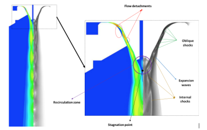
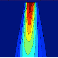
1.- Contour plot of gas velocity field with regions and shock waves indicated
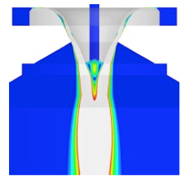
2.- Subsonic velocity field
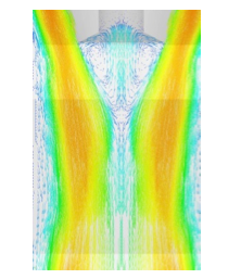
3.- Velocity field, recirculation zone
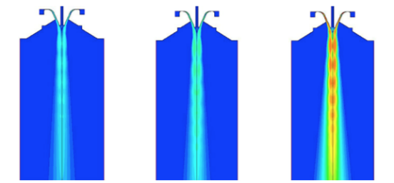
4.- Velocity fields for different gases and equal atomization pressure: argon (left), nitrogen (center) and helium (right)
The CFD simulation capabilities allow Ceit to design its own atomization nozzles and to provide technical support to companies looking for the development of new nozzles or the improvement of the ones they currently use. Ceit has extensive experience in close-coupled atomizers with either convergent or convergent-divergent nozzles.
Simulation of whole chamber flow. Anti-satellite systems
Ceit offers its simulation experience and knowledge for the development of anti-satellite systems, which may improve the quality of the powders by increasing the circularity index, the apparent density and flowability.
The presence of satellites in powder has a detrimental effect on its rheological properties, which is of paramount importance in additive manufacturing. o Because the power needs to be spread in very thin layers by a blade or roller, the presence of satellites can adversely affect the manufacturing process by creating pores or other imperfections that may degrade the mechanical properties and compromise the consistency of the whole process.
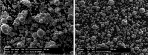
Powders produced under the same operating conditions, without anti-satellite system (left) and with anti-satellite system (right).
It is known that the presence of satellites in powder is mostly due to the re-entry of fine particles in the atomization area, where they are captured by larger particles during the solidification process. The recirculation flow responsible for this process can be discovered by simulating the gas flow in the whole atomization chamber. The knowledge of the flow path and velocity is an invaluable tool for the optimum dimensioning of the atomization chamber, o for choosing the most appropriate placement of the discharge tube, and for the eventual dimensioning of a gas recirculation loop.
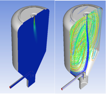
Velocity contour plot (left) and streamlines (right).
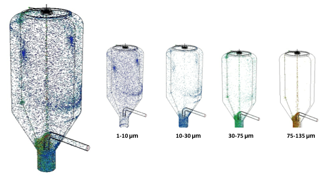
The capacity of the gas flow to drag finer particles into the atomization area can be determined by using a multiphase model. CFD multiphase simulations in which solid spherical particles of different diameters are injected below the melt nozzle reveals that the finer particles are easily dragged by upward streams to the spray area.
Experimental validation
Ceit has the equipment needed to validate its CFD simulation results via techniques such as particle image velocimetry (PIV), global sizing velocimetry (GSV) and high-speed imaging.
Different fields obtained with the PIV technique:
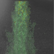
a) Particle displacement
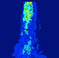
b) Instantaneous velocity field
c) Mean velocity field
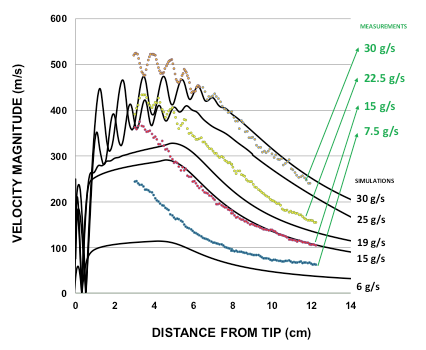
Comparison between the velocities with the PIV technique and those predicted by CFD simulations.